Intel Arc B580 firmware debugging, part 2 (opromdata & VBT dissection)
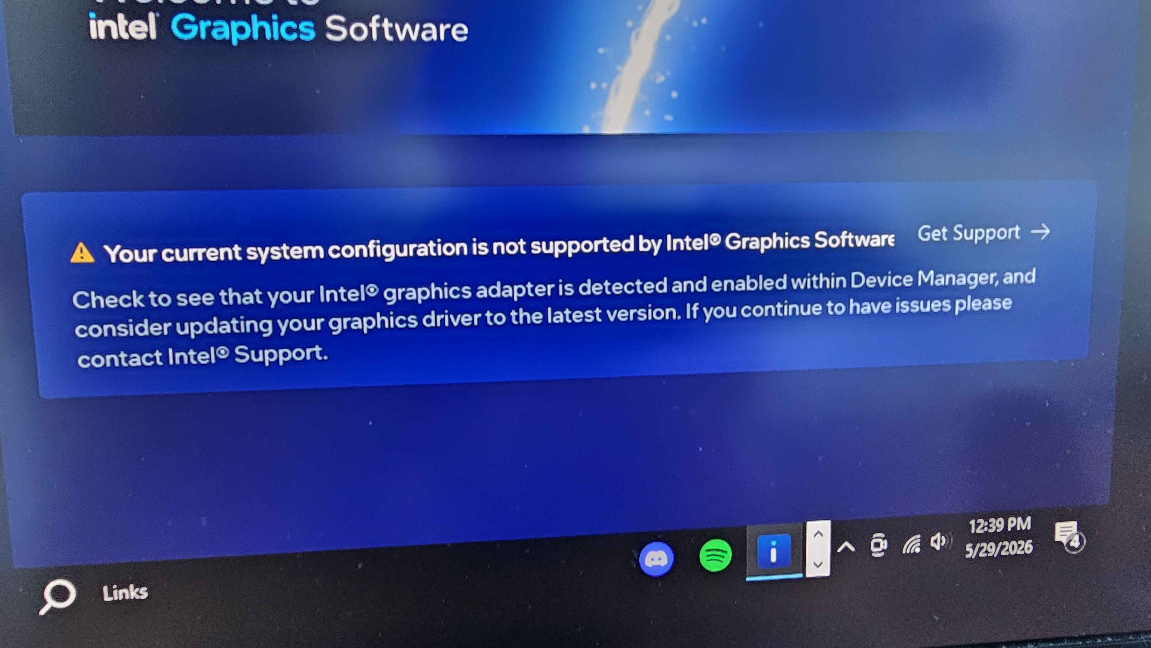
The GSC reflash got the card online, but two problems stuck around. PCODE still failed on some cold boots,
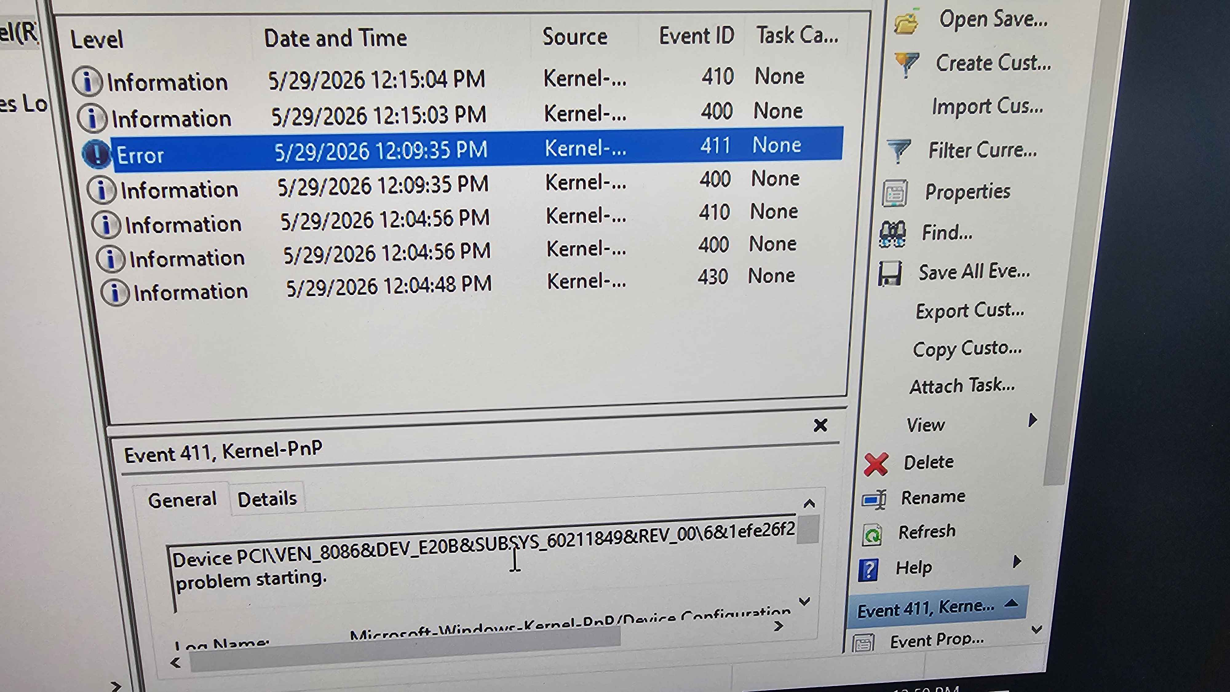
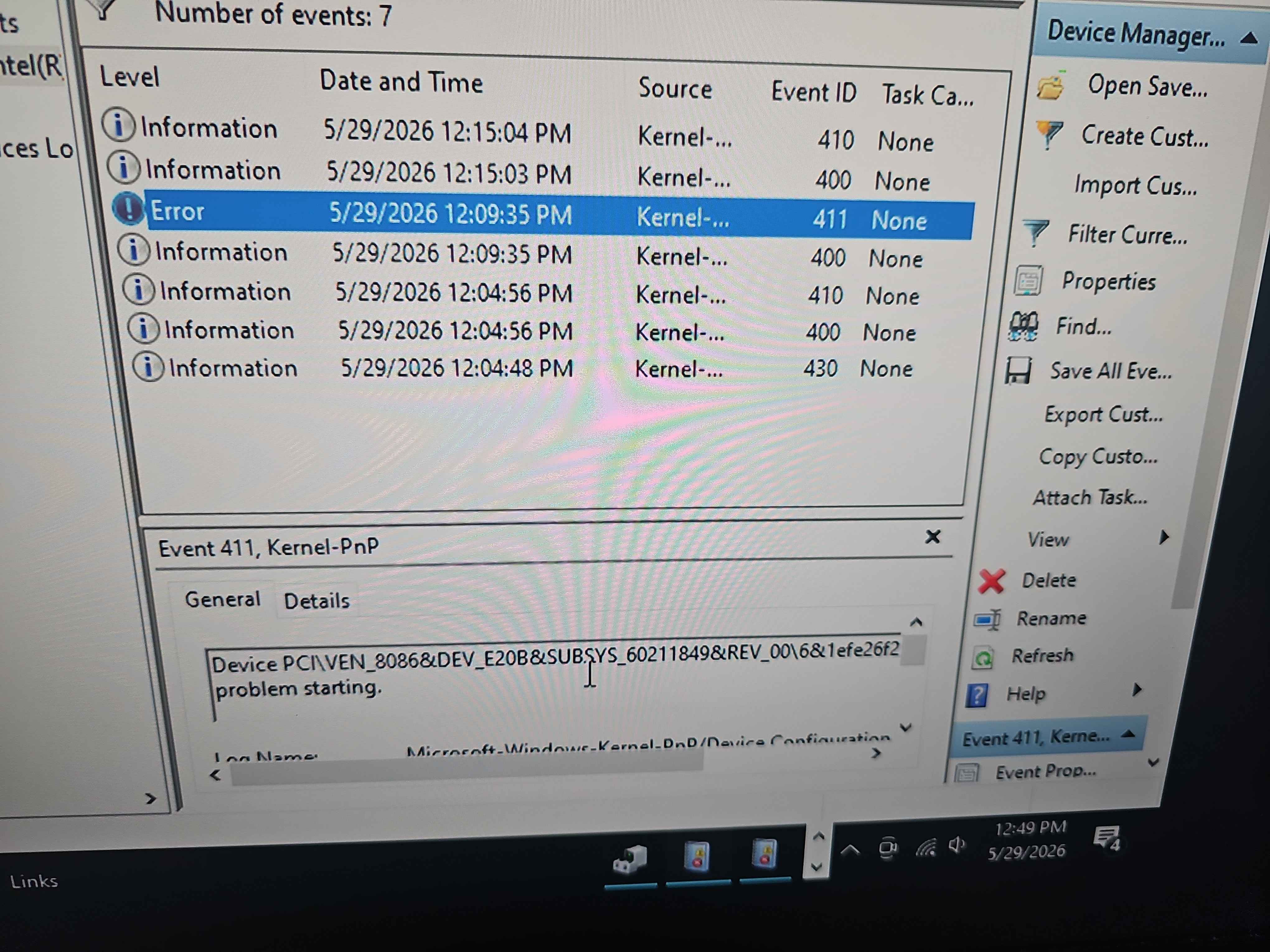
and about 90 seconds after the desktop loaded, GuC would crash in a loop no matter what I was running:
guc_exec_queue_timedout_job, seqno=213, in no process [-1].
Narrowing the remaining problem
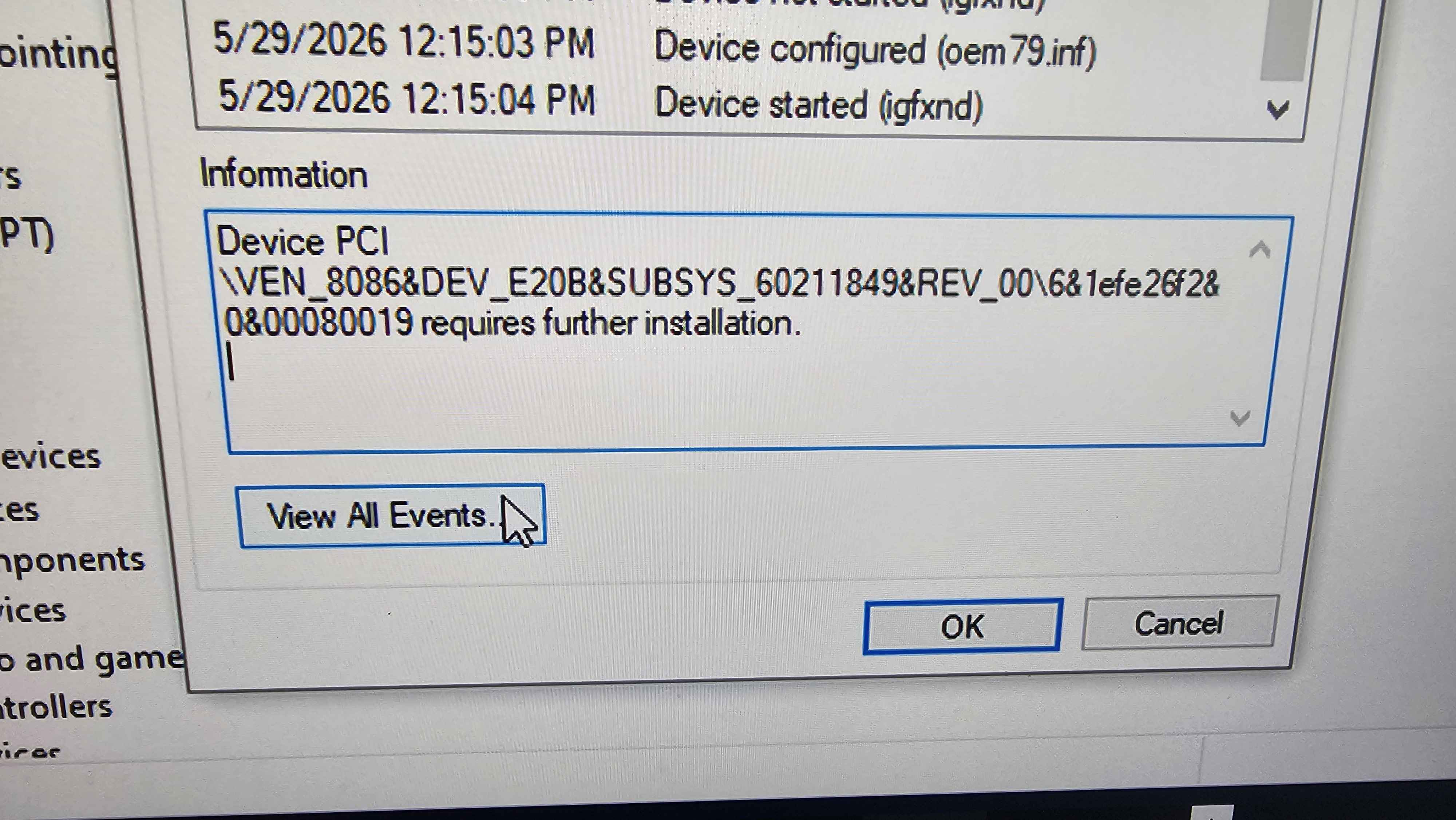
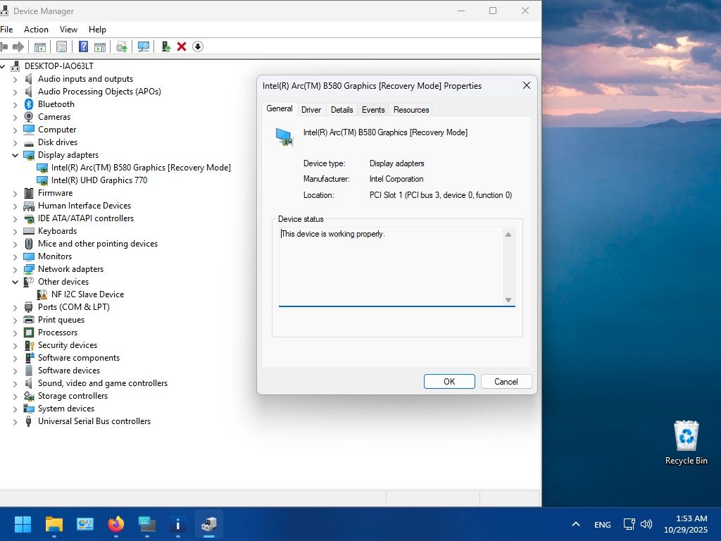
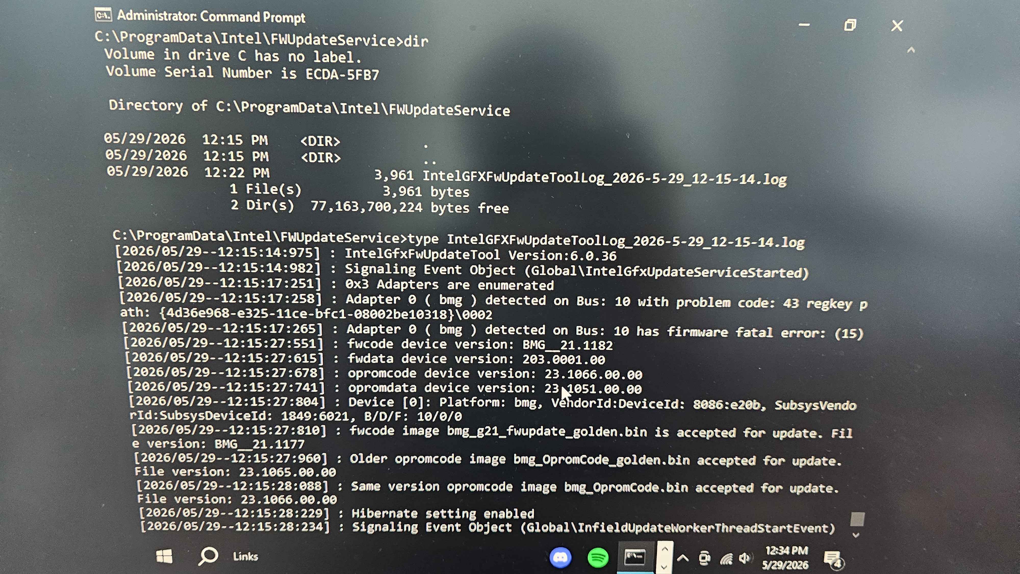
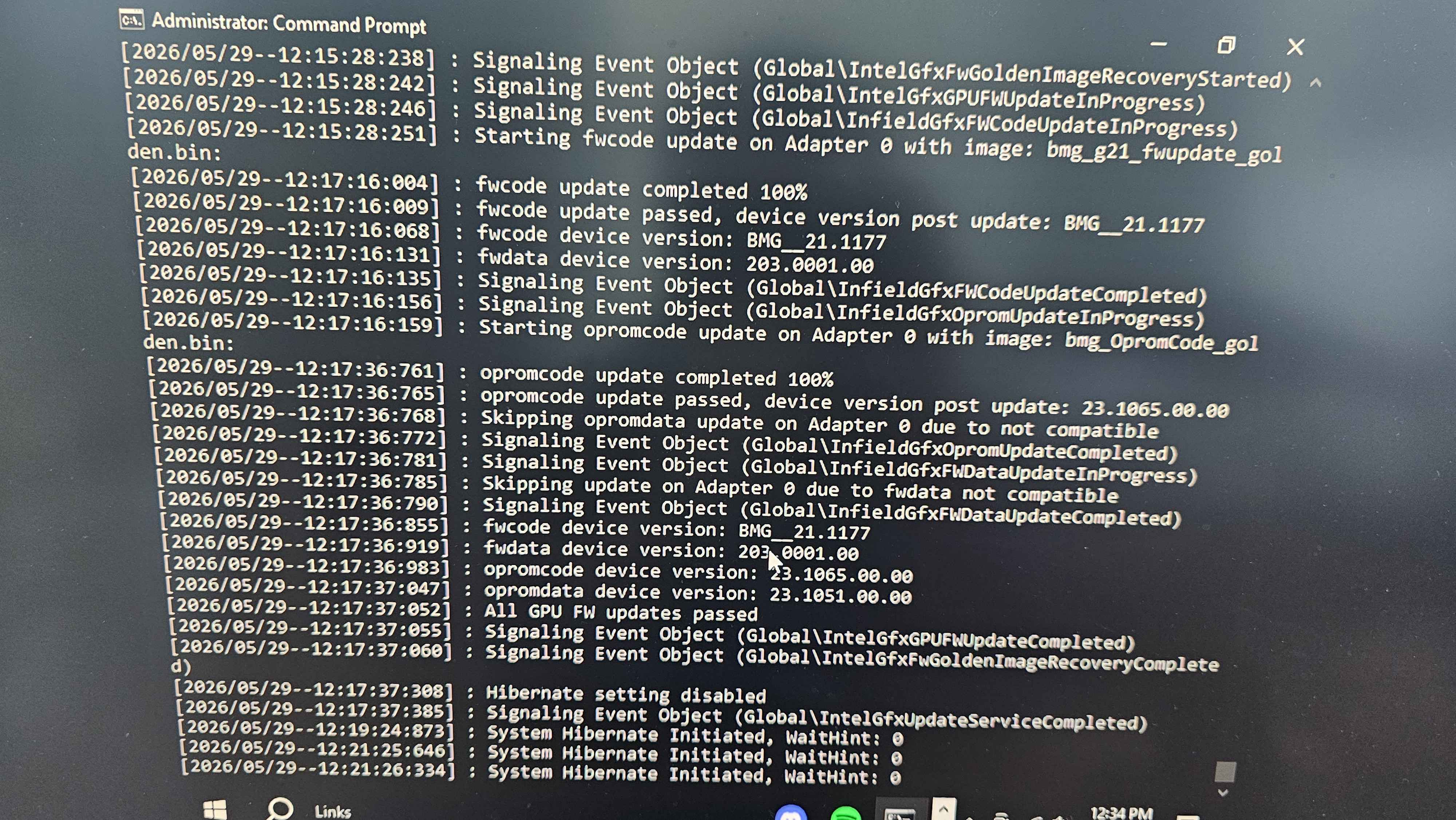
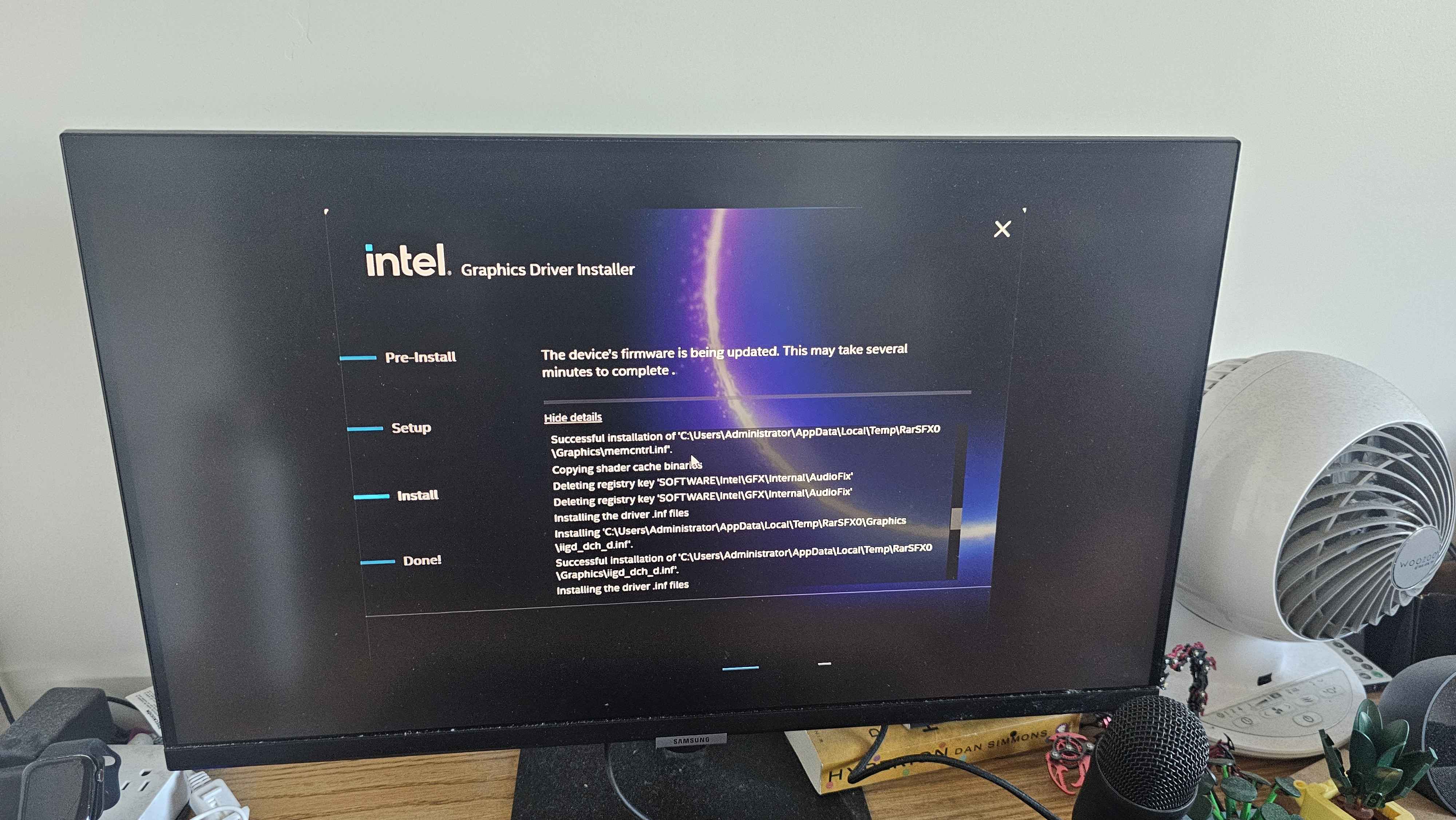
Intel's Windows recovery tool (IntelGFXFwUpdateTool v6.0.36) had already flashed fwcode and
opromcode back to the golden image versions, but it skipped fwdata as incompatible.
Nothing on either OS had ever touched opromdata.
According to fwupd GitHub issue #9889, opromdata and fwdata are 4-ID matched, meaning
they're tied to the board partner's subsystem vendor and device IDs. The ASRock Challenger B580 is
1849:6021, and Solaris17's Arc-Firmware repo lists it as "Unknown Version" with no matching
opromdata. So the card was running a generic reference opromdata that was never meant for the Challenger.
My theory: GuC reads power state transition tables from opromdata during init. If those tables don't match what the ASRock hardware expects, GuC times out waiting for a transition that never finishes. The dirty shutdown after that leaves the card in a bad state, and PCODE fails on the next cold boot. That would make both symptoms one chain of failures.
Getting the reference opromdata
I pulled bmg_e20b_1100_config19.bin from Solaris17's repo. It's the generic e20b opromdata and
the closest public match to what the Challenger should have. The file is 65,536 bytes (64KB).
Binary structure
The file has two layers. The first 2,048 bytes (0x0000 to 0x07FF) are an Intel Code
Partition Directory ($CPD) manifest, with an OROM.man manifest entry, a
VBT entry (1,344 bytes) and VBT.met metadata (1,220 bytes). There's a
$MN2 Intel manifest header at 0x338, which means this region has an RSA signature
blob. If the card checks that signature when flashing, any patch here gets rejected.
The other 63,488 bytes (0x0800 to 0xFFFF) are a normal PCI Option ROM. It starts with
the 55 AA signature at 0x0800, and the PCIR data structure at 0x081C
gives vendor 0x8086 (Intel). This is the part that can be patched.
VBT structure
The Video BIOS Table header is at absolute offset 0x283C, with the signature
$VBT BATTLEMAGE. The header fields:
- Version: 100
- Total VBT size: 7,287 bytes (ends at
0x44B3) - Checksum byte:
0xF7at absolute offset0x2856, which has to be recomputed after any patch - BDB offset from VBT start:
0x0030, so the BIOS Data Block header is at0x286C
The BDB header signature is BIOS_DATA_BLOCK, version 257.
BDB block map
I found twenty blocks in the VBT, which together account for all 7,239 bytes of BDB content:
| Block | Name | Absolute offset | Size |
|---|---|---|---|
| 254 | BIOS strings / version info | 0x02882 | 234 |
| 1 | General Definitions | 0x0296F | 10 |
| 253 | GPU caps / memory config | 0x0297C | 66 |
| 2 | General Definitions 2 | 0x029C1 | 405 |
| 252 | Header flags | 0x02B59 | 122 |
| 9 | SFI / pipe config | 0x02BD6 | 100 |
| 10 | Child Device Table | 0x02C3D | 203 |
| 12 | OEM Custom Block | 0x02D0B | 19 |
| 20 | Unknown | 0x02D21 | 170 |
| 27 | Panel / pipe timings | 0x02DCE | 814 |
| 40 | DisplayPort Table | 0x030FF | 34 |
| 42 | EFP Table (external display) | 0x03124 | 1,366 |
| 43 | MIPI Table | 0x0367D | 305 |
| 44 | Unknown | 0x037B1 | 136 |
| 46 | Unknown | 0x0383C | 304 |
| 51 | Unknown | 0x0396F | 9 |
| 52 | Compression / DSC Table | 0x0397B | 822 |
| 56 | HDMI Level Shift | 0x03CB4 | 210 |
| 57 | Unknown (likely DP/PHY config) | 0x03D89 | 1,154 |
| 58 | Driver Features | 0x0420E | 674 |
Blocks worth patching
Block 27 (panel/pipe timings, 814 bytes) has repeating 20-byte groups whose values look like power state
timing parameters: 0x07D0 (2000), 0x000A (10), 0x01F4 (500),
0x1388 (5000). If anything is causing the GuC idle timeout, it's probably these. If the
Challenger expects different transition timing, GuC would stall waiting for a state change that doesn't
arrive in time.
Block 10 (Child Device Table, 203 bytes) is all zeros except the entry size byte. That means no ports are hardcoded, which is odd for a shipping card and might confuse the display topology at init.
Block 58 (Driver Features, 674 bytes) holds capability flags, including PSR, DC states and GuC submission config.
Block 56 (HDMI Level Shift, 210 bytes) is almost all zeros after the first byte (0x0d), so it
looks like HDMI transmitter levels just aren't filled in for this reference build.
Will the GSC accept a patched file?
The big unknown before flashing any patch is whether the GSC validates opromdata when it's written. The
$CPD manifest region has what looks like an RSA signature. If the GSC checks it on opromdata
writes the same way it does for fwcode, a patched file gets rejected no matter what's in it.
Two things make me think opromdata is checked less strictly. igsc reads opromdata back from the
card through /dev/mei1 with no problem. And the whole point of 4-ID matching is to let board
partners customize this region after the chip is made, which would be a pain if every board needed its own
RSA signature.
Next step is the CH341A flash programmer. Dumping the chip from another ASRock B580 Challenger answers two
questions: what the right VBT looks like for this hardware, and whether ASRock's $CPD signature
region differs from the Solaris17 reference. If the signature bytes match, I can flash a patched file with
igsc. If they don't, I need another approach.
Where things stand
- GSC firmware: stable at 21.1182 after the igsc reflash on Linux through
/dev/mei1 - fwcode / opromcode: golden image recovery versions from the Windows flash (21.1177 / 23.1065)
- fwdata: never updated, since the Windows tool skipped it as incompatible
- opromdata: still the generic Solaris17 reference, not ASRock's own Challenger version
- PCODE: still fails on some cold boots, probably because of the GuC crash on the boot before
- GuC: still crashes at idle, and I think the opromdata power table mismatch is the cause
Now waiting on the CH341A to dump the opromdata from a second ASRock B580 Challenger.
Sum pics: